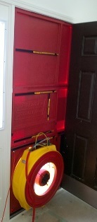
 When one starts off doing energy audits, it generally takes them awhile to get a set system in place so they don’t forget a step. One of the biggest issues for many is making sure there diagnostic equipment is not only hooked up properly, but the settings are correct, especially for the manometer.
While there are numerous versions of manometers out there, the two primary ones in use are from Retrotec (my choice) & from the Energy Conservatory. Both have there pros & cons especially when it comes to setup. With that here is a quick look at both of their offerings & then a pictorial on why settings matter.
The DG-700:
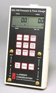 Looking for a good very basic setup, the DG700 might be a good choice for you. The biggest issue for many is remembering where you plug in the hoses for each type of test & untangling them all. As for running tests and generating results on the spot, most hook this directly up to a laptop & allow it to control everything.
The DM2:
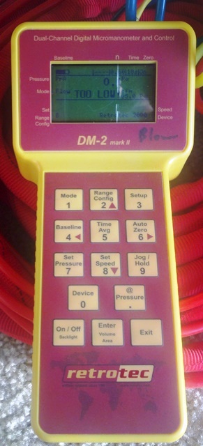 Until recently the DM2 has been Retrotec’s main manometer for all their equipment. Whereas their competitions has a basic screen & runs best off a laptop, this one has many of those features built in (though I got to say I hardly ever most of the other features). The other nice item is how they color code & bundle the tubes & cables for each type of equipment making life much more easier for hooking up everything.
The only real downside besides one getting lost looking at the panel is pulling all those tubes so you can go run a balance test, or check pressure differences. 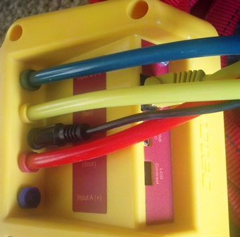
The DM32:
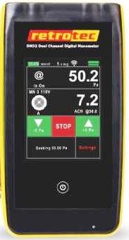 Oh I cant wait to get my hands on one of these. This is the newest manometer from Retrotec which not only has wireless access built in but also has a touchpad screen. Heh, who knows maybe they will send me one to test (hint hint). As an FYI, & under the believe it or not category, have no fears but you can add Wi-Fi to the DG-700 – no seriously, it plugs into that 80’s style serial port on the very top – as for speed, well…
Why Settings Matter:
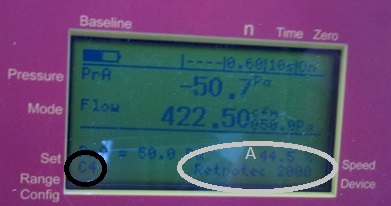 One item I generally always check before starting a test is which ring is chosen (Black Circle). In this case I was on my third blower door test for the day & figured it was still on the proper ring but as soon as I saw the number I realized something was off as I expected to see something in the 1000+ CFM range. Fortunately not only did I realize this straight off but as one final step before snapping the picture for code purposes I verify all my settings.
 One item I do to eliminate issues is I have a manometer for each piece of equipment that requires one. With this one can delete out the other pieces of equipment so you don’t have to worry about a setting getting changed. That is also one reason why you will see the word ducts, or blower door written on the manometer. Ahh but what happens if I need to use another piece of equipment, no big deal as they are still saved in the system & a quick return to defaults resets them back as an option.This & many other items can be learned from reading the manuals (see links above) or even better catching a webinar or other training class from the respective manufacturers. While training providers might provide a few tips, nothing beats what you can learn from the actual company that designed the systems. One item I do to eliminate issues is I have a manometer for each piece of equipment that requires one. With this one can delete out the other pieces of equipment so you don’t have to worry about a setting getting changed. That is also one reason why you will see the word ducts, or blower door written on the manometer. Ahh but what happens if I need to use another piece of equipment, no big deal as they are still saved in the system & a quick return to defaults resets them back as an option.This & many other items can be learned from reading the manuals (see links above) or even better catching a webinar or other training class from the respective manufacturers. While training providers might provide a few tips, nothing beats what you can learn from the actual company that designed the systems. |
As for the grey circle, the 44.5 next to the A stands for the fan speed & that is worth checking as a number to low can impact the actual results – the harder the fan has to run to get to the pressure required the better. One item I do not have to ever check is right below that & that is which piece of equipment I am using as the manometer uses that & the ring chosen to actually figure out the CFM’s (see tip above).
This is the actual result for this home which gave them a 4.53 ACH50 reading thus meeting Illinois Energy Code requirements
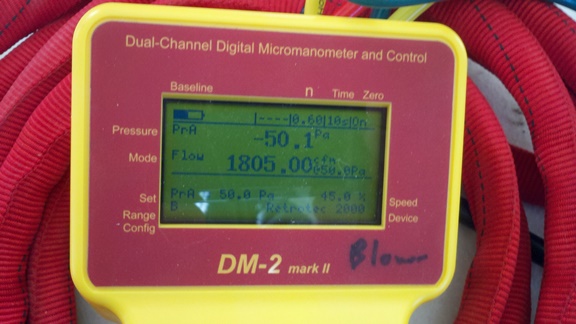
This is what happens when you choose a smaller ring than is actually used, the numbers are remarkably lower. In this case only 25% of the actual result. While the builder wouldn’t mind having these results if they are ever questioned later there would be a lot of “splaining to do”…
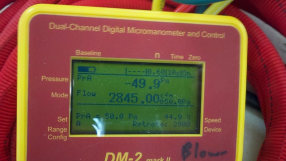
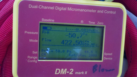 This is what happens if you choose a larger ring than what you are using – instead of the 1805 CFM listed above the leakage rate is now 2845 which would result in a fail.
A quick look at the the full range
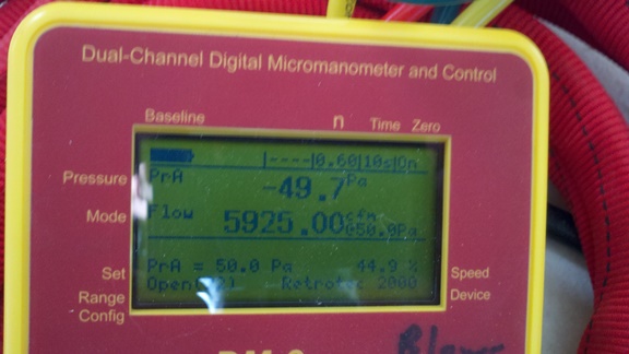
Going with fan completely wide open – Open Ring – 5925 CFM
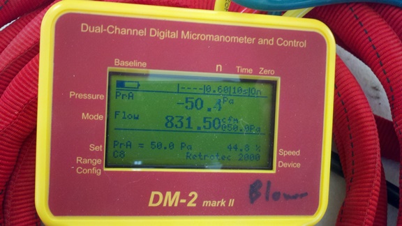
Ring C8 @ 831.5 CFM
Ring C6 @ 640.5
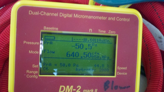
This one, C4 (pictured at top,) & the one below are ones we generally have to use for Multi-Point tests where we need readings that start around 15 Pa & what we would typically use for Passiv Haus testing as they require such tight construction. Ring C2 @ 244 CFM
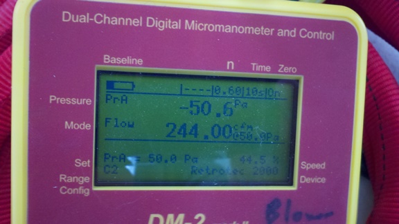
Ring C1 @ 142 CFM
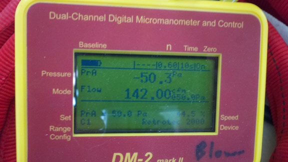
Heh, Energy Conservatory, eat your heart out – no need for us to use a duct blaster & special setups for super tight houses… Yeah those are so rare it really isn’t ever used but as we are running down all the rings — L4 @ 38.3 CFM – just like above, same house, same pressure, just wrong setting
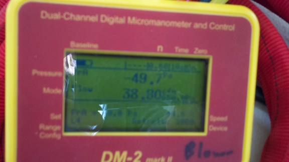
Wow now we are in duct testing measurements which also can have the same issue – L2 @ 21.75 CFM
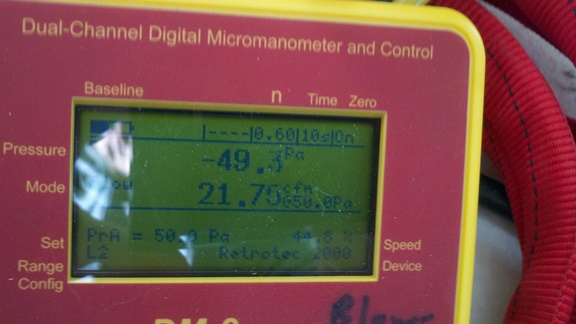
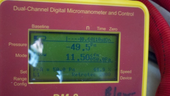
The smallest opening possible – L1 @ 11.5 CFM
 So what happens if you realize after the fact that oops, you messed up say by looking at the picture or…? Well what many training organizations like is if you actually record the “fan pressure” instead of the actual CFM measurement & use a flow conversion table (Energy Conservatory / Retrotec – page 55). Personally I don’t like the lack of accuracy & if you look at the table you can easily figure it out. Last tip, always grab a shot of the door setup along with your reading to help make sure you got it right. So what happens if you realize after the fact that oops, you messed up say by looking at the picture or…? Well what many training organizations like is if you actually record the “fan pressure” instead of the actual CFM measurement & use a flow conversion table (Energy Conservatory / Retrotec – page 55). Personally I don’t like the lack of accuracy & if you look at the table you can easily figure it out. Last tip, always grab a shot of the door setup along with your reading to help make sure you got it right. |
